Stormwater detention has been used as a strategy for managing urban stormwater runoff since the early 1970s. Originally, detention ponds were designed for larger storm events (10-year, 25-year, 50-year, or even 10-year). By the early 1980s, stormwater detention ponds were also being designed to improve water quality, specifically suspended pollutants.
The following blog post outlines the general process of designing a stormwater detention pond. It is worth noting that many municipalities throughout the United States have published their own stormwater best management practice (BMP) design standards. Engineers and landscape architects should reference such documents when preparing stormwater BMP design standards.
Types of Stormwater Detention Pond Facilities
Detention ponds can be designed in many shapes and sizes. An aboveground detention basin typically consists of a depressed area (or hole) with an earthen berm. In areas where there is not sufficient area for a detention basin, an underground detention basin may be necessary. Underground detention structures are typically comprised of large pipes or prefabricated chambers.
Detention Ponds vs. Retention Ponds
Detention ponds capture water and release it slowly. Thus, detention ponds are dry most of the time. In contrast, retention ponds maintain a permanent pool of water.
Construction Types
The type of pond construction technique implemented depends on the location of the proposed pond.
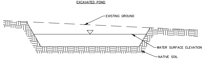
Excavation Pond
An excavated pond is constructed by digging into the earth as shown below. In areas with high groundwater, the excavated hole may fill with water even when there is no rainfall.
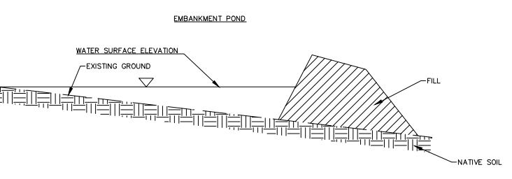
Embankment Pond
An embankment pond is constructed by adding a levee between two hillsides. This pond should not be constructed next to a channel with a significant amount of runoff because, in these cases, the risk of damage is great.
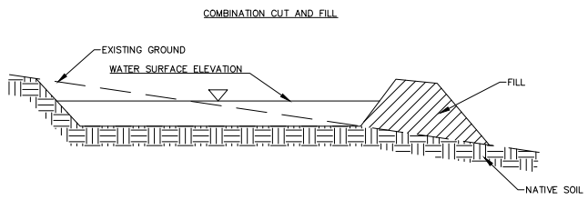
Combination Pond
These ponds are constructed using a combination of cut and fill.
Design Considerations
The design criteria for detention ponds vary widely by geographic area. In the United States, the design requirements for a detention pond are typically adopted at the county level. However, despite the varying regulations, the general rule is that the peak discharge from an undeveloped site (for a specific design storm) should not be exceeded after the site development. Without stormwater BMPs to slow down the rate of stormwater runoff, this would not be possible.
Pre-Development vs. Post-Development
As a watershed is developed, the rate at which stormwater runoff enters receiving waterbodies increases due to the increase in impervious area. The purpose of structural stormwater best management practices (BMPs) such as detention ponds is to capture and store stormwater runoff so it can be released more slowly. This reduces erosion and minimizes flooding. Many municipalities will require that a stormwater BMP is designed in such a way that peak discharges are equal to or less than pre-development conditions. It is important to note that even if such peak discharge requirements are met, detention ponds do not decrease the runoff volume. They merely slow the water down.
The pre-development versus post-development criteria must be met for a specific design storm event.
Design Storm
The design storm for a detention pond is usually specified in the county regulations. For example, a county may require that post-development peak flows be less than pre-development peak flows for the 10-year event. In addition, an emergency overflow structure may be required for a larger storm such as a 100-year event. Some places even require overflow structures that can convey the 500-year storm!
Freeboard
Freeboard is defined as the vertical distance between the maximum water surface elevation, which is often determined through hydraulic modeling during the design phase, and the top of the dam or emergency spillway. Some jurisdictions and reviewing agencies have freeboard requirements for large storm events (e.g., the 100-year storm or even the 500-year storm).
Pond Size
The size of the pond depends on the volume of runoff the pond is designed to capture. This runoff volume, in turn, depends on the design storm. There are several ways to determine the volume of stormwater runoff from a site. The most common methods are the Soil Conservation Service (SCS) Curve Number Method and the Simple Method.
Multiple ponds may be necessary to meet the requirements of a particular agency or municipality. In such cases, ponds can be connected in series such as the outflow hydrograph for one pond is the inflow hydrograph for the next pond downstream.
Drawdown Time
The drawdown time is the time it takes for the detention pond to empty or drain (commonly 24 to 48 hours). This time is often specified by local authorities. Longer drawdown times typically result in improved pollutant removal rates. However, longer drawdown times tend to result in less attractive facilities as there will be little to no vegetation on the bottom of the pond. Drawdown time is calculated by dividing the water quality volume by the outflow capacity (cfs) of the low flow outlet.
Components of Stormwater Detention Ponds
The physical components of a detention facility depend on the site conditions and the local regulations. The following sections describe some of the most common elements of a stormwater detention pond.
Outlet Structures
The detention pond outlet structure allows for water to discharge from the pond at a controlled rate. In the past, detention ponds have been designed for a single storm event. These ponds had very simple outlet control structures. Today, it is common for detention ponds to contain outlet structures that contain separate components that convey a water quality (low-flow) event, a larger storm such as the 10-year or 25-year storm, and a very large storm event such as the 100-year event. These components are discussed in the following sections.
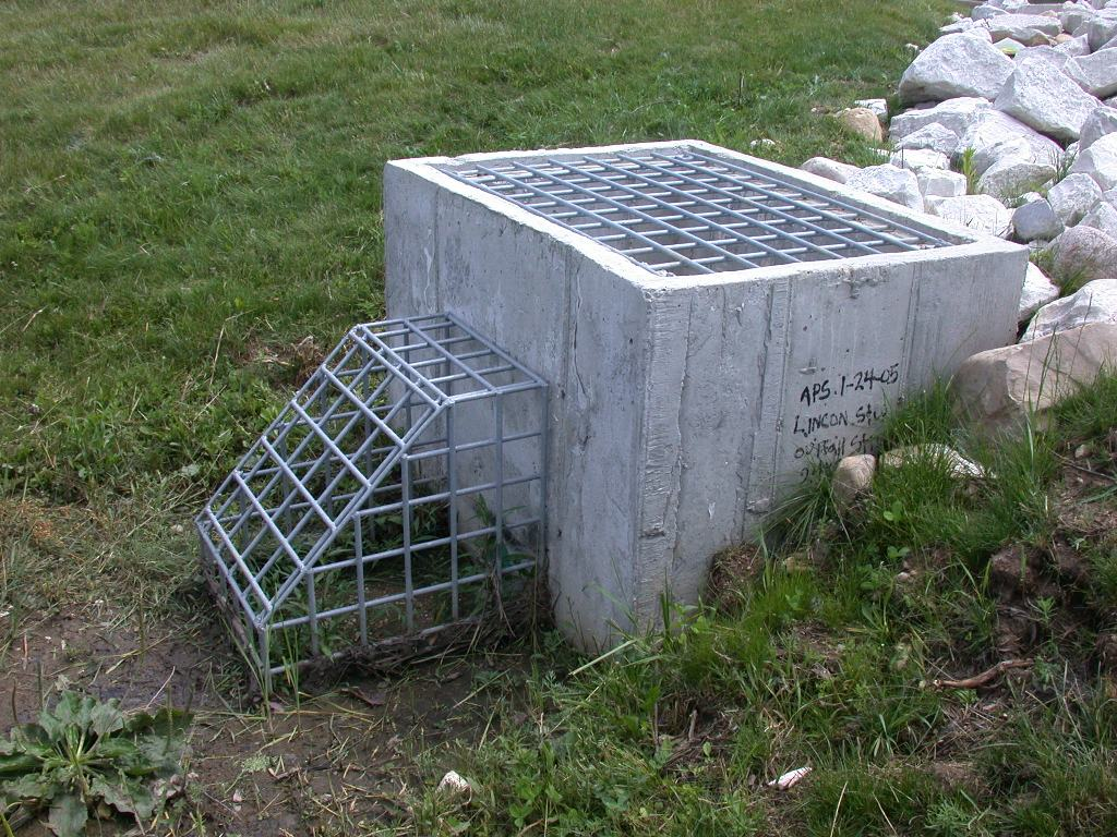
Riser Structures
Riser structures such as the one shown in the image below can be made of concrete or a corrugated metal pipe (CMP). A riser structure is typically designed to convey low-flow events. When the water level reaches the elevation associated with the water quality event, the flow may enter the riser structure through an orifice. When the water level reaches a higher elevation, enter the top of the structure as shown below. It is a good idea to put trash racks on a riser structure to prevent clogging.
An outlet pipe is placed at the bottom of the riser structure to convey the flow entering the riser structure away from the pond. These pipes typically daylight at a nearby ditch or stream. The outlet pipe may be under inlet control or outlet control depending on the downstream conditions. For pipes with diameters less than 12 inches, the orifice equation can be used to represent culvert hydraulics. This assumption is valid if the headwater depth to pipe diameter ratio is at least 1.5 and if outlet control (tailwater) effects are negligible (Brown et al., 1996).
Overflow Spillways
The purpose of an overflow spillway is to safely convey discharges associated with large storm events. Overflow spillways are often referred to as emergency spillways because they are designed for extreme precipitation events (e.g., the 100-year storm, 500-year storm). For technical guidance on designing effective overflow spillways, refer to the United States Bureau of Reclamation’s Design of Small Dams.
Pond Bottoms and Side Slopes
The sides of a detention basin should be sloped at an angle of 3H:1V or flatter. This will encourage vegetation growth on the sides of the basin, which will minimize erosion. Steeper slopes can also be difficult to maintain.
The bottom of a detention pond should be sloped to ensure that water flows to the outlet structure. This will ensure that the detention pond will completely drain between storm events. Consider adding a low-flow channel from the inlet to the outlet structure to ensure the pond bottom drains completely.
Dam Embankments
As previously mentioned, many stormwater detention ponds are constructed by excavating and grading a depression/hole in the ground. In these cases, the resulting pond has no dam embankment per se. In other cases, a stream or localized depression is dammed to create a pond. When designing such a dam, it is recommended that the engineer or designer consult a geotechnical engineer.
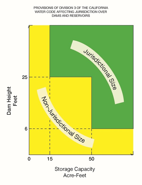
When designing a stormwater detention pond, it is also important to consider whether the dam embankment will become a jurisdictional dam. In almost all cases, you do not want to create a jurisdictional dam as these structures have a lot of permitting costs associated with them. In California, jurisdictional dams are regulated by the Division of Safety of Dams (DSOD). The following chart summarizes the criteria for a jurisdictional dam in California.
Pond Liners
As previously discussed, the purpose of a detention pond is to capture stormwater runoff and release it slowly rather than allowing a significant amount of water to infiltrate into the ground. For this reason, detention ponds located in areas with well-draining may need an impermeable layer to prevent groundwater contamination. Ponds can be lined with clay or an impermeable liner. EPDM rubber liners are a good option because they are long-lasting and environmentally friendly. It should be noted that rubber liners should be covered with a layer of sand or fine soil to protect them from potential damage (e.g., punctures).
Routing Procedures For Detention Ponds
Routing describes the process of developing a stage versus discharge relationship to describe the detention pond’s outlet hydraulics. The discharge from a detention pond depends on the water surface elevation (stage) of the pond and on the characteristics of the outlet(s). The steps for performing a routing analysis are as follows:
- Calculate the post-development inflow hydrograph. The inflow hydrograph describes the flow rate entering the pond. Inflow hydrographs can be developed by calculating a unit hydrograph. A unit hydrograph can be developed for gauged watersheds or you can create a synthetic unit hydrograph. There are various synthetic unit hydrograph methodologies available. The most common ones are those proposed by Clark, Snyder, Singh, and the NRCS.
- Next, calculate the storage volume rating curve (stage vs. storage) relationship for the pond. This involves measuring the area of each contour and calculating the associated storage volume using the average end area method or the conic method.
- Then calculate the outflow rating curve (stage vs. discharge) relationship for the pond outlet(s). This step involves calculating outflow for each foot of elevation using the orifice equation and/or the weir equation.
- Finally, establish the Storage Indication Method to establish the relationship between stage, storage, and discharge.
Modeling Stormwater Detention Ponds
Stormwater detention ponds are typically modeled using hydrologic modeling software such as HydroCAD or HEC-HMS. More complex software packages such as XPSWMM might be required when modeling larger drainage systems that include detention ponds. PondPack is a Bentley product used by some engineers to model and design detention ponds. Although I have never used PondPack, I have found Bentley products to be very user-friendly in general. However, licenses are expensive.