Site grading is an essential skill for civil engineers to master. This is because grading is an extremely important part of the land development process. Site plans prepared for the purpose of constructing a new development typically include several sheets. One of these sheets will include the grading and drainage plan. In some cases, grading and drainage will be separated into two plans. The grading plan will include information related to the proposed ground surface, and the drainage plan will include information about storm drain pipes (e.g., invert elevations, erosion control, pipe sizes, etc.).
As previously mentioned, site grading is an important skill for civil engineers to master. Even so, “grading and drainage” is not a required class at many schools that offer civil engineering degrees. This means that many entry-level/graduate engineers find themselves learning about site grading “on the job.” In my opinion, it is quite frustrating to have to learn such a fundamental skill at your first professional job. On the other hand, grading is both a science and an art in the sense that there is more than one correct way to grade a site. However, there are some basic principles that should be followed when developing a grading plan for your project. The following blog post will describe some of the basics of developing a grading plan.
What is a grading plan?
Grading typically involves removing topsoil and associated vegetation before scraping and forming the ground into the desired surface formation. A grading plan is the part of a construction drawing set that describes the earthworks activities that will be conducted as part of the construction of a project. As such, the grading plan will show design elevations, swale locations, dimensions of water features such as ponds, and drainage patterns.
Landscape grading involves sculpting the land to direct water away from buildings and other structures. A lot grading plan specifies the pad elevation, lot type, and surface gradient for each home within a land development project.
Who prepares a grading plan?
For land development projects, grading plans are typically prepared by a civil engineer. For large-scale projects, grading plans must be stamped by a licensed professional engineer (PE). Soil engineers, geotechnical engineers, and structural engineers are also civil engineers and may stamp a grading plan. For landscaping/gardening projects, grading plans may be prepared by landscape architects or landscape designers. In California, grading plans for projects that involve less than 5,000 CY of excavation AND do not support any structures can be prepared without a civil engineer’s stamp.
Site Grading Terminology
The following list defines some terms commonly used in grading plan preparation.
Backfill – a term to describe the material used to refill an excavated hole or trench.
Berm – a raised piece of land or mound of soil placed for the purpose of diverting water away from a structure or feature.
Borrow Pit – an area used to remove earth that will be used for fill material in another location.
CAD – Computer Aided Design (CAD) software used to draft construction plans. Some examples of CAD programs include AutoCAD (most common), MicroStation, and BricsCAD.
Contour – A line that indicates areas of the same elevation. Major (index) contours are placed at a certain interval (typically every 5 or 10 feet) and are bolded. Minor contours are the contours placed between major contours. Styling major and minor contours differently helps the user interpret a topographic map or grading plan more easily. Contours are typically shown at one-foot intervals for land development projects. Existing contour lines are often depicted in a lighter color and are dashed. In contrast, proposed contour lines are typically darker in color and are typically solid lines.
Cut and Fill – Earthwork that is to excavated is referred to as “cut” while excavated material that is placed is referred to as “fill.” It is important for an engineer to understand the cut and fill volumes generated by their grading plan because these volumes will impact the cost of the project.
Easement – An area or property designated for a particular purpose (e.g., power easement, sewer easement)
Existing Conditions – The existing condition of a site is often depicted by a topographic survey.
Existing Grade – The elevation of the ground surface prior to any earthwork activity.
Fine Grading/Finish Grading – Fine grading, which is also referred to as finish grading, is performed after rough grading and ensures that the ground surface elevations match what is shown on the construction plans as closely as possible.
Final Grade – The elevation of the proposed ground surface.
Limit of Disturbance (LOD) – A boundary line that shows the point at which the proposed contours meet the existing contours. Areas outside of the LOD should not be touched. The area within the LOD is important for permitting purposes. For example, a disturbed area greater than one acre will often require a grading permit.
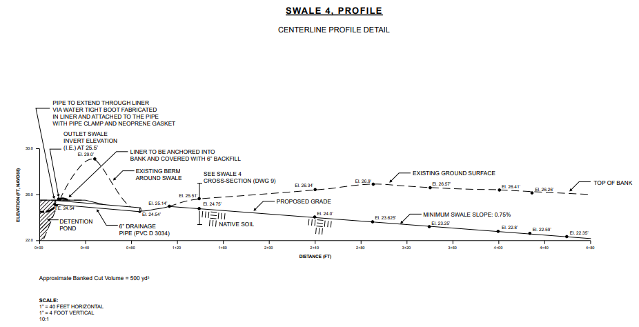
Profile – A profile depicts elevations along an alignment (which is often the center of a channel, stream, or road). Profiles are typically provided for storm drains, channels, retaining walls, bank protection, or roads. An example of a profile view is shown below. Typically, profiles are presented above the plan view.
Proposed Conditions – The designed condition.
Retaining Wall – A rigid wall that supports soil laterally. In general, retaining walls that are 4 feet in height or smaller can be designed by a civil engineer with little to no geotechnical analyses. However, larger retaining walls require the consultation of a licensed structural or geotechnical engineer.
Rough Grading – Earthwork activities that involve excavating the general shapes and slopes shown on the grading plan. In this way, rough grading could be considered a “first pass” towards achieving the elevations shown on the grading plan.
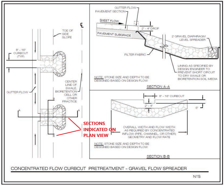
Section – A section will show a cross-sectional view of the proposed ground surface. A section includes relevant dimensions and elevations. Sections are typically shown for stormwater features and highway projects. An example of a section is shown below.
Setback – the minimum distance which a building or other structure must be from a road, stream, floodplain, or any other place which is deemed to need protection.
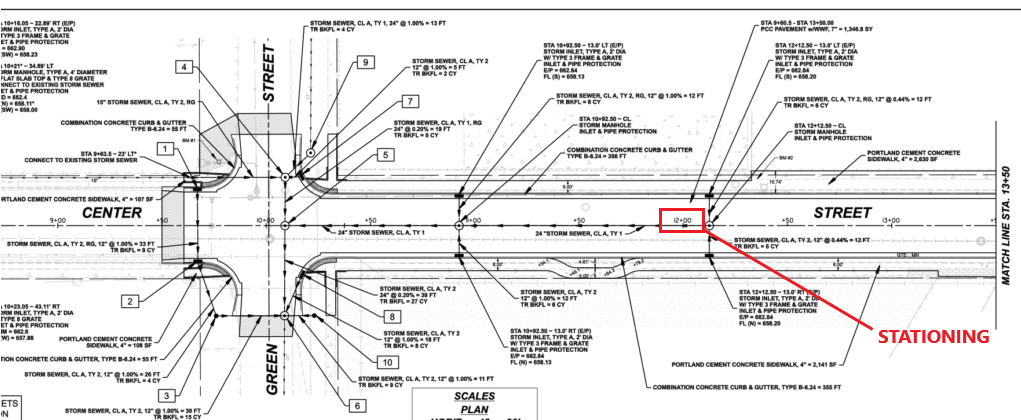
Stationing –
Swale – an open channel that conveys flow.
Slope – the amount of vertical change over a certain horizontal distance. It is often calculated as rise/run. On grading plans, longitudinal slope is usually expressed as a percentage, and side slopes are usually expressed as horizontal: vertical (H: V).
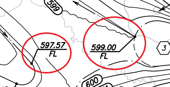
Spot Elevation – Spot elevations, which are also called spot grades, refer to the exact elevation at a particular point. Typically, spot elevations are reported to the nearest hundredth (0.01) of a foot. An example of a spot elevation is shown below.
Survey – A topographic survey, which is often referred to as the “survey,” is performed before preparing a grading plan. The survey depicts the existing condition of the site and includes the following information: existing elevations/contour lines, location of existing structures, location of existing trees and vegetation, and the location of existing utilities.
Components of a Grading Plan
Because each project is different, the way you set up the grading plan for a particular project in CAD may differ slightly. For example, more complex projects may require more details and sections to adequately convey the design intent. Similarly, some reviewers may require more detailed construction drawings before issuing relevant permits. In general, your grading plan should include the following components:
- Title block – the title block should include information about the project, the stamp of the supervising professional engineer (P.E.), the date, plan size, and the sheet number.
- North Arrow
- Scale Bar
- Proposed contour lines
- Relevant spot elevations
- The existing contours/topographic survey data should be included underneath the proposed contour lines. In addition, information about the survey (e.g., name of the surveyor, date of the survey, and vertical datum) should be included in the notes.
- Sections
- Profile lines
- Limits of disturbance (LOD)
- Location of structures and infrastructure
- An estimate of the quantities of excavation and fill, adjusted for anticipated swell or shrinkage.
- Location of stockpiles and borrow pits.
- Relevant details for stormwater best management practice (BMP) features and storm drains (if drainage is included in the grading plan)
- Indicate and riprap aprons or energy dissipation structures.
- Location of any streams or watercourses.
- HEC-RAS sections (relevant for open channel and bank projection projects)
It is worth noting that the requirements for a grading plan can differ by agency. For this reason, I recommend checking the reviewing agency’s website for a grading plan submittal checklist or something similar before submitting your grading plan.
What paper size should I use for a grading plan?
Like most construction drawings, grading plans are typically 24 inches by 36 inches in size (Arch D). If your site is large, the grading plan/grading and drainage plan may be printed on more than one sheet.
How To Set Up A Grading Plan
Most civil engineering firms will have CAD templates for their construction drawings. Before you begin setting up the actual grading plan, make sure you are using the correct template.
Next, use the XREF command in AutoCAD to reference the existing contours/topographic survey (and any other relevant information such as stream centerlines, aerial imagery, building footprints, or utilities). Make sure you select “overlay” rather than attachment when using XREF. This is important because selecting Attachment causes XREF that’s inserted into the drawing to carry through when you XREF the current drawing into another plan set/drawing. In short, attachments can get messy, so it is best to stick with overlay.
After referencing all of the relevant drawings, it is time to begin the actual site grading process. For me, this involves drawing contours on top of the existing surface. It is important that your proposed contour lines are either closed or “tie in” to the existing contour lines. In other words, there should never be any “floating contours” on your grading plan.
Many grading plans are prepared in AutoCAD Civil 3D. The following sections describe AutoCAD Civil 3D tools commonly used when preparing a grading plan in AutoCAD Civil 3D.
Creating a Surface in Civil 3D
To generate sections and profiles in Civil 3D, the user must first create a surface. It is also necessary for performing cut and fill calculations. Create a surface for the existing condition and a surface for the proposed condition. This will allow you to generate profiles and sections that show the existing ground surface and the proposed ground surface. The following video describes how to create a surface in AutoCAD Civil 3D.
Creating Alignments in Civil 3D
An alignment is a line that represents the centerline of a road, channel, or other feature. You must draw an alignment before generating profile views. The following video describes how to draw an alignment in AutoCAD Civil 3D.
Generating Sections in Civil 3D
Detail sheets often contain sections of the grading plan. AutoCAD can generate these sections automatically as shown in the video below.
Generating Profiles in Civil 3D
A profile allows you to see the elevations along a horizontal alignment. They are commonly shown for linear features such as roads, streams, swales, channels, and pipes. The following video demonstrates how to generate profile views in AutoCAD Civil 3D.
This PDF was created by the Natural Resource Conservation Service (NRCS) and outlines the steps for creating a profile in AutoCAD Civil 3D.
Calculating Cut and Fill Volumes in Civil 3D
The purpose of estimating cut and fill volumes is to minimize the amount of earthwork performed on-site and to minimize the amount of soil that will have to be imported or exported as these measures will reduce the cost of the project. In some cases, the grading plan is simple enough that cut and fill volumes can be calculated using manual calculations (e.g., the average end area method). However, in other cases, calculating cut and fill volumes manually can be complex. Fortunately, AutoCAD Civil 3D can calculate cut and fill volumes for you by comparing the existing surface and the proposed surface. The following link contains a video and associated information that describes how to calculate cut and fill volumes in AutoCAD Civil 3D.
Rules of Thumb for Grading Plans
The primary purpose of grading is to sculpt the land in such a way that stormwater runoff is conveyed to an appropriate storage facility or the storm drain system. This will minimize flooding. However, the engineer must also how the slope of the proposed ground will affect maintenance operations and the end users (e.g., shoppers in a parking lot). The following rules of thumb serve as a starting point. It is important to check the requirements of the reviewing agency.
Slopes
| Feature | Slope | Notes |
| Access Drive | Maximum of 8% | It is important not to make the main access driveway too steep because cargo may shift and cause damage. |
| Parking Lots | Maximum of 3% | Steep slopes can cause shopping carts to hit cars and can make it difficult to keep car doors open. |
| Landscaped Areas | Maximum of 3H:1V (33%) | Slopes steeper than 3:1 can be difficult to maintain. In some cases, it may be okay to specify slopes steeper than 3:1 as long as they are stabilized (e.g., lined with riprap, erosion and sediment control blankets, or retaining walls. |
| Asphalt Area | Minimum of 1.5% | Asphalt areas with slopes flatter than 1.5% tend to develop depressions that cause puddles. |
| Concrete Curb | Minimum Slope of 0.5% | Ensures adequate drainage. |
Soil Cover for Utilities
Minimum soil cover for utilities differs depending on the agency and geographic location. In cold climates, minimum cover depth requirements are deeper to minimize the chance of pipes freezing during the winter months. More soil cover is required in areas where vehicles will be driving over the pipes and when pipes are installed in watercourses.
| Utility Type | Minimum Cover |
| Sewer | 2 to 4 feet from the top of the pipe |
| Water | 2 to 4 feet from the top of the pipe |
| Electrical | 1 ft |
| Gas | 18 to 36 inches |
The minimum cover for a rigid drainage pipe such as reinforced concrete pipe (RCP) is the greater of 1/8 the outside diameter of the pipe or 12 inches, when there is only soil or flexible pavement above it. When a rigid pavement is over the RCP, the minimum cover is 9 inches from the bottom of the pavement. The minimum cover for a plastic drainage pipe located in an unpaved area is the greater of 1/8 the inside diameter of the pipe, or 12 inches. For locations with pavement, the minimum cover is the greater of one half of the inside diameter of the pipe or 24 inches.
Americans With Disabilities Act (ADA) Requirements
It is important to ensure that your grading plan adheres to the requirements of the Americans With Disabilities Act (ADA). For example, the ADA requires that all businesses and public use wheelchair ramps adhere to a 1:12 slope ratio. This means that for every inch of vertical rise, there must be 12 horizontal inches of horizontal distance.